
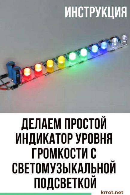
The proposed sound volume level indicator can be used in any acoustic system for visual control. It is used in the same way as the light and music design of acoustic systems. It can be assembled in just a few minutes and without spending a lot of money on parts.
Content:
 Read also: Landscaping your site with your own hands - (130+ Photo Ideas & Videos) + Reviews
Materials for manufacturing
In order to make a level indicator, you will need:
- output LEDs such as Foton 5 mm in five colors - 10 pcs.;
- resistors 680 Ohm - 10 pcs.;
- electrolytic capacitors 100 uF 25 V - 2 pcs.;
- diode 1N4007 - 2 pcs.;
- zener diode for 20 V - 10 pcs.;
- a piece of chipboard;
- soldering iron;
- drill with 5 mm drill;
- wire cutters;
- insulated wires;
- tweezers.
Step 1. We make an LED ruler
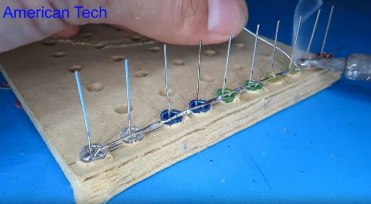
In a piece of chipboard along the line at a distance of about 10 mm. we drill 10 holes with a diameter of 5 mm (according to the size of the LED head).
We insert LEDs in pairs (by color) into the holes, with negative leads in one direction.
We bend one of the negative terminals alternately towards the adjacent LED and solder the contacts.
We bend the positive terminals of the diodes and bite off with wire cutters.
We cut off one of the leads of the resistors and solder them in order to the positive leads of the LEDs.
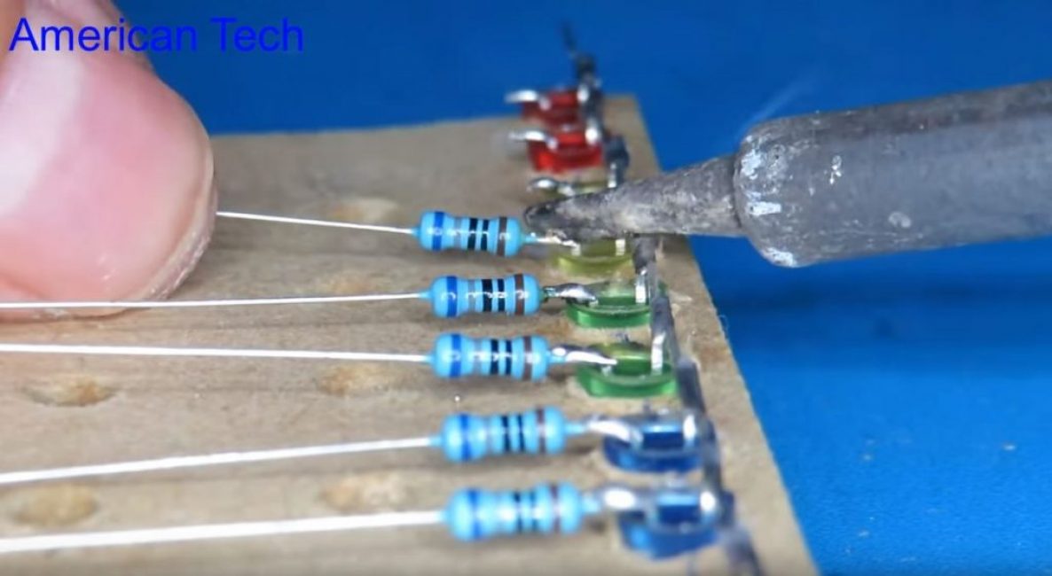
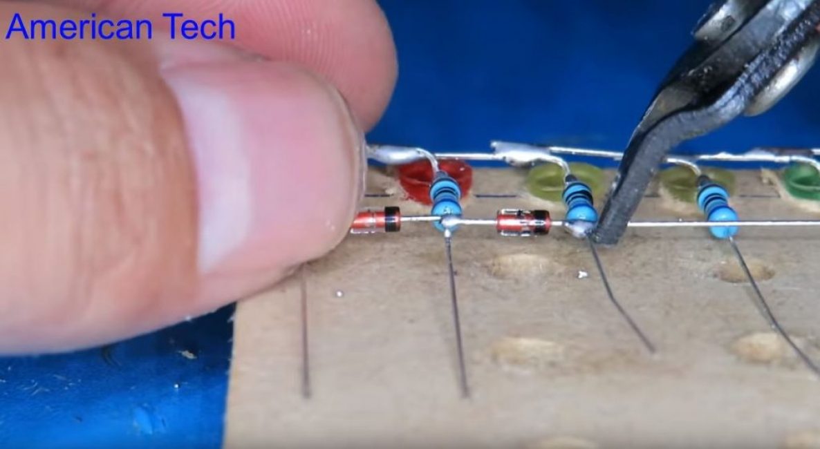
Between adjacent resistors, we solder the zener diodes in turn, observing the polarity, biting off the excess part of their conclusions.
We bite off the extra pieces of the leads of the resistors.
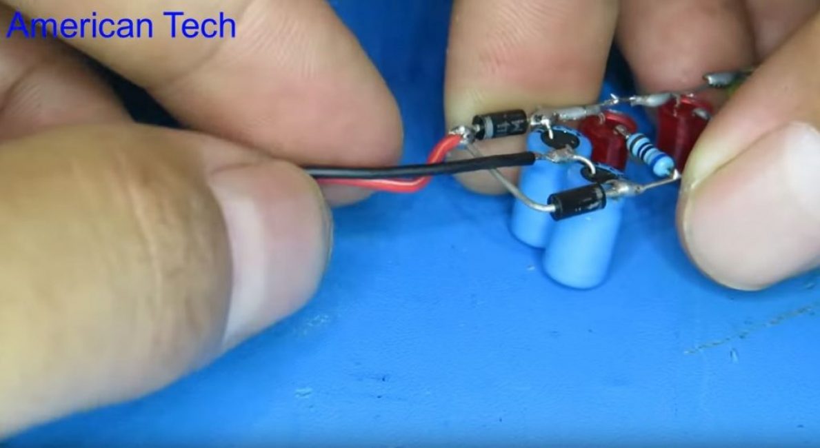
Step 2 Mounting the voltage doubler
We connect two capacitors in series and connect them to the beginning of the line.
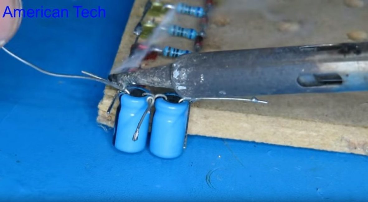
Solder the diodes, observing the polarity.
We solder the diodes by bending the end of one to the other. We bite off unnecessary ends with wire cutters.
Carefully remove the indicator from the template with tweezers.
To the junction between the capacitors, solder the insulated wire. The second wire is soldered to the junction of the diodes.
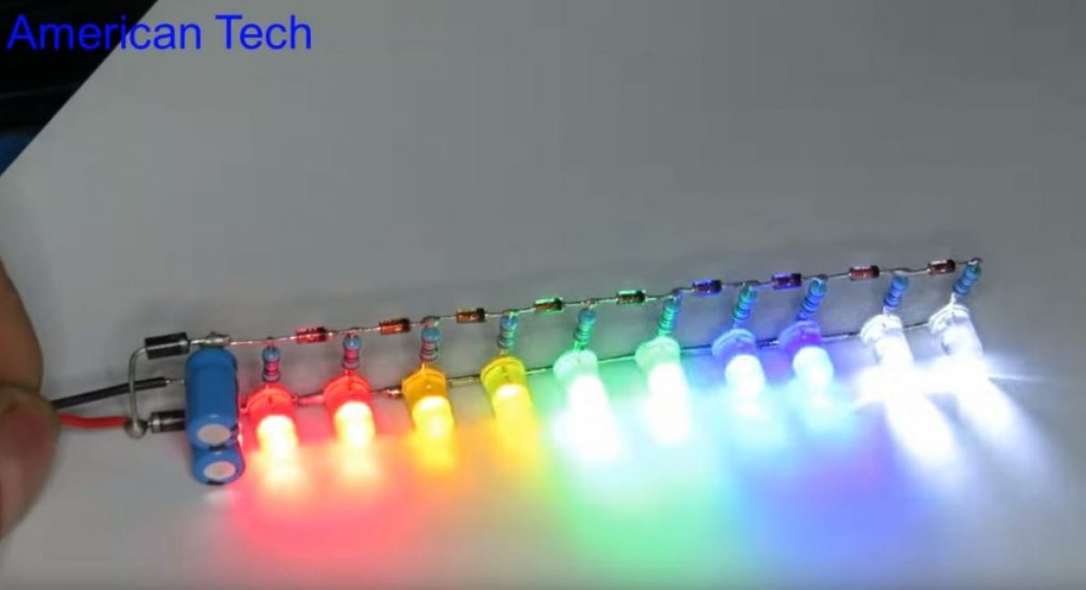
Step 3. Checking the indicator robots
We connect the indicator wires to the speaker terminals and turn on the sound.
At a low sound volume, only a part of the LEDs should light up.
At maximum volume, all LEDs will light up.

Making a level indicator without transistors
Level indicator without transistors and microcircuits


